Sabiya is a useful Gulf reference plant because it has run hard for two decades and its operating logs are well-documented in MEW reliability reports. The 280 MVA / 220/15.75 kV GSUs at the site cycle through ambient swings from 12 °C in February to 53 °C in August, with starts-per-year an order of magnitude higher than a baseload European unit would see. The thermal-cycling spec that emerged from Sabiya now travels through every GCC combined-cycle bid.
Thermal Overload in a 50°C World
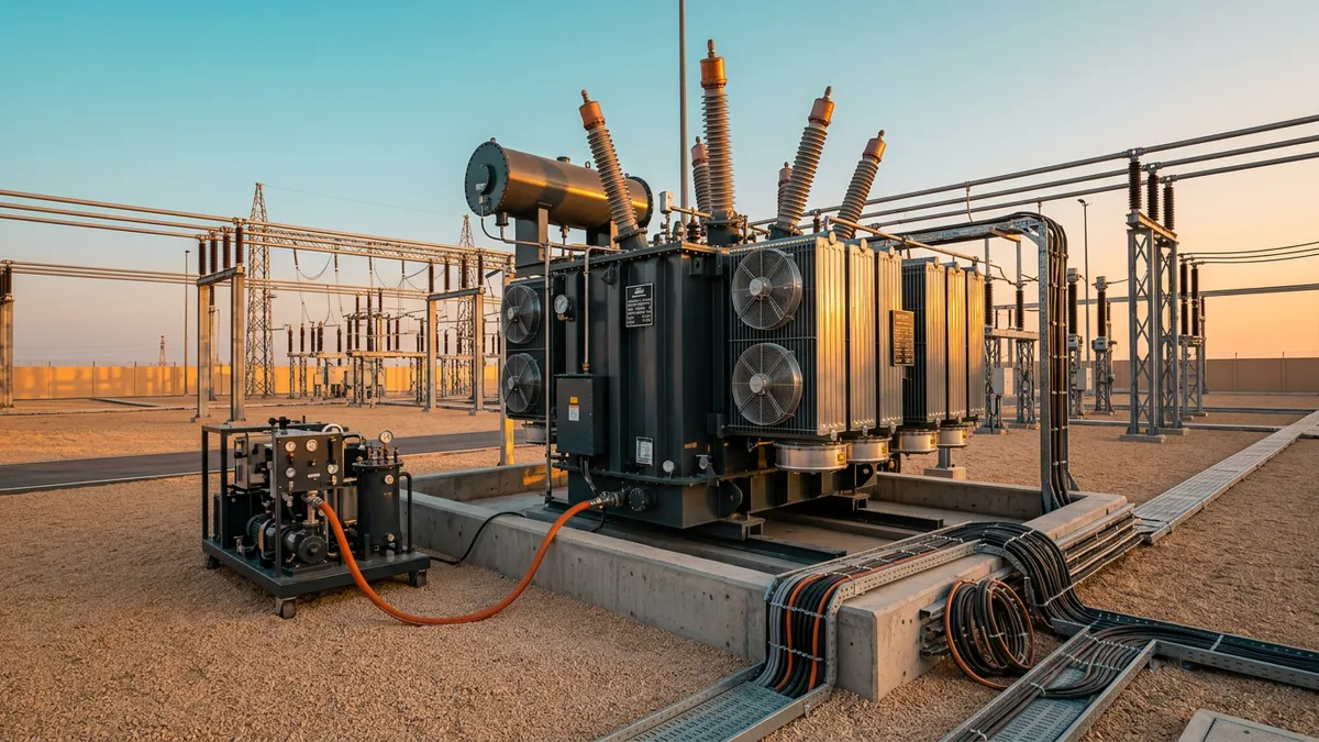
- Problem: A 400 MVA GSU is a giant heat source. Operating it in a climate where the ambient shade temperature regularly exceeds 50°C pushes thermal management to its absolute limit.
- Mechanism: Transformers are rated for a specific temperature rise above ambient. When the "ambient" baseline is already exceptionally high, the margin for handling operational heat (I²R losses in the windings and core losses) shrinks dramatically. The viscosity of the insulating oil changes, and the efficiency of the cooling radiators (whether ONAN or ONAF) plummets.
- Consequence: Accelerated aging of the transformer’s solid insulation (paper and pressboard) is the primary result. The rule of thumb, derived from Arrhenius’s equation, is that for every 6-8°C increase in operating temperature above its design limit, the life of the insulation is halved. A transformer designed for a 25-year life can be cooked to failure in under a decade.
- Solution: The solution lies in a conservative cooling design and verified performance. Insisting on a lower temperature rise limit (e.g., 55°C rise instead of the standard 65°C) provides a critical thermal buffer. For Sabiya, this meant specifying a cooling system (typically ONAF - Oil Natural Air Forced) with a high margin and verifying its performance during the Factory Acceptance Test (FAT). The heat-run test during the FAT isn't a box-ticking exercise; it is the single best tool for confirming the transformer can actually perform as specified in the harsh reality of a GCC summer.
The Overlooked Mechanics of the OLTC
- Problem: On-Load Tap Changers (OLTCs) are essential for regulating grid voltage, but they are complex mechanical devices attached to a static piece of electrical equipment. They are, by far, the most likely component of a GSU to fail.
- Mechanism: Most failures originate in the diverter switch, where the load current is interrupted and transferred. Each operation creates an arc, which carbonizes the surrounding oil and erodes the contacts. In a plant like Sabiya, where units may adjust output to follow grid demand, the number of tap-change operations can be far higher than in a classic baseload plant.
- Consequence: A failed OLTC forces the entire GSU offline. Repair is not a simple matter; it’s an invasive, oil-draining, multi-day surgery that requires specialist technicians and results in millions in lost generation revenue.
- Solution: Modern specifications can mitigate this risk significantly.
1. Technology Selection: Specifying a vacuum-type OLTC instead of a conventional oil-immersed diverter switch is the single biggest upgrade. Arcing is contained within a sealed vacuum interrupter, which eliminates oil carbonization and dramatically extends the maintenance interval (e.g., from 50,000 operations to 300,000 or more).
2. Operational Profile: The procurement specification must clearly state the *expected number of annual operations*. This allows the manufacturer to design the contact system and maintenance schedule appropriately. Assuming a low number to save initial cost is a false economy.
3. Condition Monitoring: A modern GSU spec should include online monitoring for the OLTC, tracking motor energy, operating time, and acoustic signature to detect developing mechanical faults before they lead to failure.
For a critical asset like a GSU, treating the OLTC as an afterthought is an invitation for future trouble. Ask our engineering team; they spend more time diagnosing OLTC issues than any other single transformer component.
When "Standard" Impedance Isn't Enough
- Problem: The GSU impedance is one of the most important parameters for the entire electrical system design, yet it's often treated like a standard catalogue value.
- Mechanism: The percentage impedance (%Z) of the transformer governs two critical factors: its voltage regulation under load and the amount of current it will pass during a system short circuit. For a 2.4 GW plant, the potential fault contribution into the 400 kV grid is immense.
- Consequence: An incorrectly specified impedance has severe network-wide effects.
- Too Low: The transformer will contribute an excessive amount of current during a fault on the 400 kV network. This could exceed the short-circuit withstand rating of downstream circuit breakers and other 400 kV switchgear, leading to a catastrophic failure of substation equipment.
- Too High: The transformer will have poor voltage regulation, causing a larger voltage drop as the generator loads up. This can impact the unit's ability to export reactive power and maintain stability, potentially leading to MEW grid code violations.
- Solution: There is no "standard" impedance for a GSU of this scale. The value must be derived from detailed system studies, including load flow and short-circuit analysis of the surrounding grid. The final %Z (typically in the range of 14-18% for a GSU this size) is a carefully negotiated figure between the plant designer and the utility (MEW). It balances fault-limiting capability with operational voltage performance, and must be specified with a tight tolerance (e.g., ±7.5% as per IEC 60076-1).
Key Takeaways
- Environment is Everything: For coastal GCC sites, specifying C5-M coatings, higher creepage bushings, and sealed enclosures is not an optional upgrade; it's essential for survival.
- Thermal Margin is Lifespan: Designing for the 50°C ambient of a Kuwaiti summer, not a generic datasheet, by specifying conservative temperature rises is the key to ensuring a 25-year operational life.
- The OLTC is Mechanical: Treat the on-load tap changer as the primary point of failure. Specifying vacuum technology and defining the operational duty cycle can prevent the most common cause of transformer outages.
The Engineer's Takeaway
At a 2,400 MW plant, the generator step-up transformer isn't just a piece of procured equipment; it is a system-critical node that defines the boundary between the power island and the national grid. Its specification is a masterclass in trade-offs—between cost and reliability, fault limitation and voltage regulation, and material science and the raw power of the Gulf’s climate.