A traction system at 2x25 kV is, electrically, a delicate balance between catenary and feeder. Etihad Rail adopted the topology to push autotransformer feeder-station spacing out to 50 km without pushing catenary voltage drop beyond the limit set by the rolling stock. The neutral-point treatment, and the way the autotransformer handles return current under fault, are the practical engineering details that make the project work.
The Voltage Drop Dilemma
The Problem: How do you power a 200 km/h train across vast, sparsely populated stretches of desert without the voltage collapsing? A standard 25 kV single-phase AC system, common in European networks, begins to show its limits in a landscape defined by extreme distances. Powering a heavy freight or high-speed passenger train requires immense current, and over long feeder sections, impedance (the AC equivalent of resistance) becomes your enemy. The result is a classic voltage drop, proportional to the current and the distance from the feeding substation.
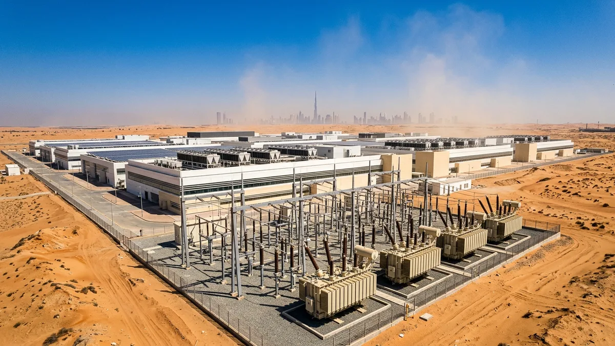
The Mechanism: For a given power demand, a lower transmission voltage necessitates a higher current (P = V × I). This higher current, flowing through the impedance of the overhead line and rails, leads to a larger voltage drop (V_drop = I × Z). It also results in significantly higher resistive losses (P_loss = I² × R). In the context of Etihad Rail Stage 2, which snakes over 600 km from the Saudi border to the Omani border, relying on a simple 25 kV system would require an uneconomical number of grid connection points and feeder substations (FS) to keep the pantograph voltage within its operational band (typically per BS EN 50163).
The Consequence: An inadequately managed voltage profile means sluggish train performance, particularly during acceleration which is the period of peak power draw. In the worst case, the voltage at the pantograph could fall below the locomotive's lower limit, causing its main circuit breaker to trip. For the system planner, it would mean building feeder substations every 30-40 km, a huge capital expenditure in terms of land, high-voltage grid connections, and equipment. The project's entire economic feasibility comes into question.
The Solution: Enter the 2×25 kV autotransformer (AT) feeding system. While the train still draws power at 25 kV from the catenary, the power is actually transmitted along the track at 50 kV. The system uses a feeder wire running parallel to the track, energised at +25 kV with respect to the rails, while the catenary itself is energised at -25 kV. This creates a 50 kV potential between the two conductors. Autotransformers, sited every 12-15 km along the track, step this voltage down. By effectively doubling the transmission voltage, the current is halved for the same power, reducing voltage drop and I²R losses by a factor of four. This elegant solution allows feeder substation spacing to be stretched to 50-60 km, dramatically improving the project's business case.
Taming Troublesome Harmonics
The Problem: Modern locomotives are no longer simple resistive loads. They are sophisticated pieces of power electronics, using variable-speed drives and AC-DC-AC converters to achieve fine motor control. As non-linear loads, they inject "dirty" power back into the grid.
The Mechanism: Instead of drawing a smooth, sinusoidal 50 Hz current, the inverters and rectifiers in a locomotive's traction drive chop the waveform, drawing current in rapid pulses. A Fourier analysis of this distorted current waveform reveals not just the fundamental 50 Hz frequency, but a whole spectrum of higher-frequency components—the 3rd, 5th, 7th, 11th, and so on. These are harmonic currents. They flow from the train, through the catenary, back through the main traction transformer at the feeder station, and are injected into the 132 kV utility grid, in this case operated by TRANSCO.
The Consequence: Unchecked harmonics are a menace to the wider power system. For the utility, their presence can lead to a cascade of problems that threaten grid stability and equipment health:
1. Overheating: Harmonic currents cause additional heating in utility transformers, cables, and capacitor banks, potentially shortening their operational life. This is a major concern in a grid already dealing with high ambient temperatures.
2. Equipment Malfunction: They can interfere with sensitive electronic equipment and ripple control systems used for utility load management.
3. Protection Nuisance-Tripping: Protection relays can misinterpret harmonic distortion as a fault condition, leading to spurious trips and costly outages.
4. Regulatory Penalties: System operators like the National Grid in the UK or TRANSCO in the UAE have strict grid codes (e.g., referencing standards like IEEE 519) that set limits on harmonic voltage distortion at the point of common coupling (PCC). Exceeding these THD (Total Harmonic Distortion) limits can result in significant penalties.
The Solution: The engineering solution is twofold: detailed modelling and targeted filtering. Before any steel is ordered, extensive harmonic analysis is performed using software like DIgSILENT PowerFactory or ETAP. These studies model the entire network, from the train's load profile to the utility grid's short-circuit level, to predict the magnitude and order of harmonic currents. Based on this analysis, harmonic filter banks are specified and installed at the feeder substations. These are typically passive filters—large capacitor and reactor banks tuned to specific harmonic frequencies—which provide a low-impedance path to shunt the offending currents to ground before they can pollute the 132 kV grid. For more complex systems, active filters that electronically inject an opposing, "anti-harmonic" current may be used. Find out more about our grid-compliant power solutions on our products page.
The Autotransformer Balancing Act
The Problem: The 12-15 km spacing of autotransformers is not an arbitrary number. It is a carefully optimised parameter that balances performance, cost, and operational safety. Placing them too far apart saves money on equipment but compromises the voltage profile. Placing them too close is wasteful.
The Mechanism: Spacing decisions are driven by sophisticated load-flow simulations that model the "moving substation" effect of a train. As a train travels from one AT to the next, the path the current takes and the load on each AT changes dynamically. The ideal spacing ensures that even when a train is at the midpoint between two ATs—the point of maximum impedance—the pantograph voltage remains within its allowable band under worst-case loading conditions (e.g., maximum acceleration of a heavy freight train on an incline).
The Consequence: Getting the spacing wrong has tangible consequences. Spacing that is too wide can create voltage-sag "pockets" along the line, impacting service. More critically, it complicates protection coordination. The protection relays at the feeder station need to differentiate between a legitimate short-circuit fault miles down the track and the very high (but brief) inrush current of a train starting up. If the zones of protection defined by AT locations are too large, sensitivity may have to be turned down, increasing the time it takes to clear a real fault.
The Solution: The answer lies in rigorous, iterative simulation and specifying the right hardware. The 12-15 km spacing was determined by running thousands of scenarios. But the autotransformers themselves are also key. These are not standard distribution transformers. They are custom-designed units, often with a centre-tapped single winding, built to withstand the unique electrical and mechanical stresses of traction duty. They must handle highly variable, intermittent loads and frequent inrush currents. For projects like this, sourcing robust, purpose-built traction transformers and autotransformers is a non-negotiable part of the system design.
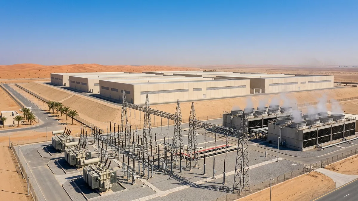
Engineering for the Rub' al Khali
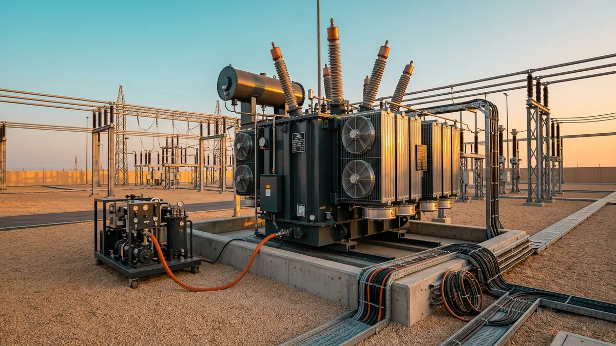
The Problem: Etihad Rail operates in an environment that is actively hostile to electrical equipment. Ambient temperatures can exceed 50°C, abrasive, airborne sand is a constant, and coastal sections of the route introduce saline humidity.
The Mechanism: Heat is the enemy of transformers. According to IEC 60076, a transformer's load capacity is directly tied to its ability to dissipate heat. High ambient temperatures reduce the thermal margin, effectively derating the equipment. Sand and dust act as insulators, blanketing cooling fins and preventing effective heat dissipation. They also wear down seals and moving parts. Finally, salt-laden air accelerates corrosion of enclosures and metallic components.
The Consequence: A standard, off-the-shelf transformer or switchgear panel will not survive long in the Empty Quarter. The result is a drastically shortened asset lifespan, a high probability of premature failure, and a maintenance regime that is both costly and dangerous to execute. A single feeder station failure can disable a 50-60 km stretch of the railway, halting all traffic.
The Solution: The solution is a "design for environment" approach, where the harsh climate is a primary design driver, not an afterthought. This involves several layers of hardening:
- Enhanced Cooling: Transformers are specified with higher temperature class insulation (e.g., Class H) and often uprated cooling systems (ONAN/ONAF/OFAF) to maintain capacity even on the hottest days.
- Sealed Enclosures: Control and protection panels are housed in enclosures with high IP (Ingress Protection) ratings, such as IP65, to prevent the ingress of dust and moisture.
- Material Selection: Liberal use of stainless steel for hardware and enclosures, along with advanced multi-layer paint coatings on transformers and steel structures, provides a barrier against corrosion.
- Prefabrication: Using pre-fabricated, containerised package substations offers an immense advantage. These are assembled and tested in a clean factory environment and delivered to site fully integrated, minimising on-site exposure to the elements and ensuring higher build quality.
Key Takeaways
- The 2x25 kV autotransformer system was the enabling technology for powering heavy-haul and high-speed trains efficiently over the extreme distances of the Etihad Rail network.
- Managing harmonic injection into the 132 kV utility grid, a consequence of modern power electronics, required detailed upfront modelling and the deployment of tuned harmonic filters.
- Equipment specifications had to be significantly enhanced—from transformer cooling to enclosure IP ratings—to ensure long-term reliability and performance in the harsh GCC climate.
The Engineer's Takeaway
The Etihad Rail power system is more than just a means to an end; it's a high-voltage transmission network that happens to be moving at 200 km/h. Its success in overcoming voltage regulation, harmonic distortion, and extreme environmental challenges offers a robust engineering playbook for the next generation of ambitious GCC rail megaprojects. For any further questions, please contact us.