The Part Nobody Photographs
Scroll through any renewable energy company's website and you'll see endless fields of gleaming solar panels stretching to the horizon. Beautiful. Inspiring. And completely useless without the equipment that most people never see.
Between those photovoltaic panels and the socket in your wall lies a chain of power conversion, transformation, protection, and switching equipment that represents 40-50% of a solar farm's total investment — and nearly 100% of its reliability risk.
Let's follow the electron.
Step 1: The Panel — DC Power at Awkward Voltages
A single solar panel produces roughly 30-45V DC. Not very useful. But string 20-30 panels together in series, and you get 600-1,500V DC — the input range for modern string inverters.
A 100 MW solar farm might have 250,000 individual panels organised into thousands of strings. The cabling alone for this stage can stretch hundreds of kilometres.
Step 2: The Inverter — DC to AC Conversion
The inverter is the heart of the solar plant. It converts DC power to AC power at grid frequency (50 Hz or 60 Hz). Modern inverters achieve efficiencies of 98.5-99% — meaning only 1-1.5% of the solar energy is lost in conversion.
But here's the challenge: inverters produce power at a relatively low voltage — typically 600-800V AC for string inverters or up to 1,500V AC for central inverters. The grid operates at 33 kV, 66 kV, or 132 kV. Something needs to bridge that gap.
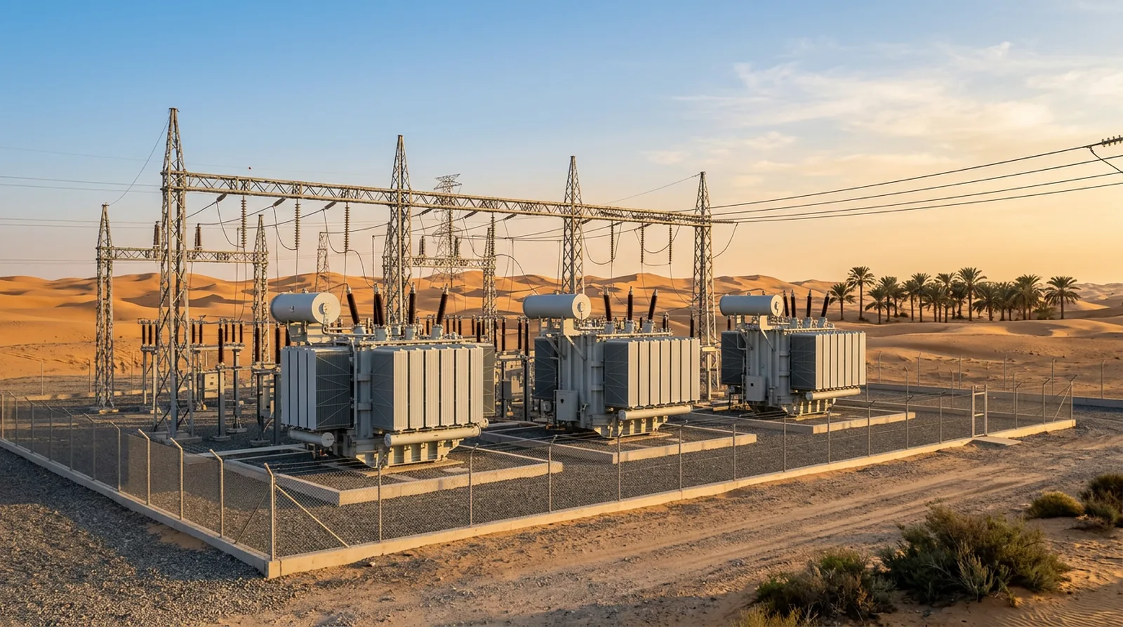
Step 3: The Step-Up Transformer — The Unsung Hero
This is where the inverter duty transformer earns its keep. These specialised units face challenges that standard distribution transformers never encounter:
- Harmonic-rich input: Inverter output contains significant harmonics — 5th, 7th, 11th, and 13th are the main culprits. These harmonics cause additional heating in the transformer, requiring K-factor rated designs or specific harmonic mitigation windings
- DC offset: Imperfect inverter switching can inject small amounts of DC current into the transformer, causing core saturation and excessive noise
- Rapid load cycling: Solar output fluctuates with cloud cover. A transformer might cycle between 20% and 100% load dozens of times per day — thermal cycling that accelerates aging
- High ambient temperatures: Solar farms, by definition, are in sunny places. Transformers operate in ambient temperatures that would be considered extreme in other applications
A typical solar farm transformer takes the inverter's 690V or 800V output and steps it up to 33 kV for collection within the solar farm. Then a main power transformer at the farm's substation steps up again to the grid voltage — 132 kV or 220 kV.
Step 4: The Collection Network — Invisible Infrastructure
Between the inverter transformers and the main substation lies the collection network: underground cables at 33 kV connecting dozens of inverter stations to a central point. The cable routing, sizing, and protection coordination for this network is a significant engineering challenge — especially when the solar farm covers 200+ hectares.
Ring Main Units (RMUs) at each connection point provide switching and fault isolation, ensuring that a cable fault in one section doesn't take out the entire farm.
Step 5: The Grid Connection — Where Regulations Get Real
The main substation is where the solar farm meets the utility grid. This is arguably the most complex part of the entire installation:
- Power transformers (typically 50-100 MVA) step up to transmission voltage
- Circuit breakers rated for fault currents of 25-40 kA provide primary protection
- Protection relays implement dozens of protection functions: overcurrent, earth fault, reverse power, anti-islanding, frequency deviation, voltage deviation, rate-of-change-of-frequency (ROCOF)
- SCADA integration connects the plant to the grid operator's control centre
- Reactive power compensation (SVCs or STATCOMs) ensures the plant meets grid code requirements for power factor and voltage support
The Numbers Behind a 100 MW Solar Farm
- Solar panels: ~250,000 units
- String inverters: ~500 units (or 10-20 central inverters)
- Inverter duty transformers: ~50-100 units (800 kVA to 3.15 MVA each)
- Main power transformers: 2-4 units (50-100 MVA each)
- 33 kV cable: 30-50 km
- Protection relays: 200+ devices
- Total BOS cost: $40-60 million (40-50% of total plant cost)
Why Equipment Choice Matters More Than Panel Choice
Here's the counterintuitive insight: panel technology is largely commoditised. The difference between a good panel and a great panel might be 2-3% efficiency. But the difference between well-specified and poorly-specified balance-of-system equipment can mean 5-10% availability loss — far more impactful on the project's IRR.
The transformer, in particular, is the single point of failure for each inverter station. A transformer failure takes weeks to replace and months to procure. Redundancy at the transformer level is rarely economically justified, making reliability the single most important specification criterion.