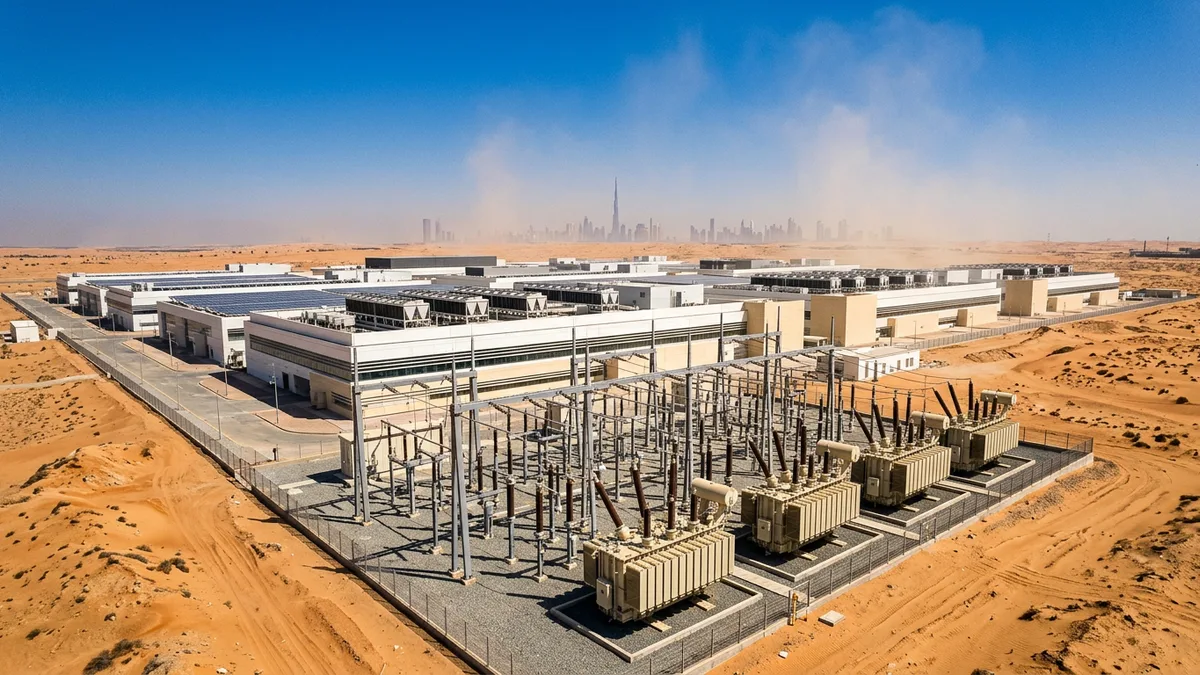
The Arabian Sea represents a geo-paradox: an immense resource of saline water adjacent to vast deserts with world-class solar potential. Connecting these natural assets to produce green fuels is not a simple matter of scale, but one of profound electrical engineering complexity. The journey from seawater to a stable, transportable green energy carrier like ammonia is a three-stage process, with each stage—desalination, electrolysis, and synthesis—demanding power in a fundamentally different form, necessitating a sophisticated, multi-family transformer architecture on a single site.
The Power Challenge of a Three-Stage Process
At the front end of the plant, seawater is drawn and purified. This initial desalination stage, typically using reverse osmosis (RO), relies on powerful pumps to force water through membranes, leaving the salt behind. These large pump motors operate on standard alternating current (AC) and represent a significant, continuous load. The second stage, electrolysis, sits at the heart of the process. This is where the purified water is split into hydrogen and oxygen using Proton Exchange Membrane (PEM) electrolysers. These electrolyser stacks are direct current (DC) devices, requiring immense, stable DC power at a specific low voltage. This creates a fundamental mismatch with the high-voltage AC power supplied by the grid. The final synthesis stage involves reacting the green hydrogen with nitrogen (separated from the air) to create a denser energy carrier like ammonia. This process, often a variant of the Haber-Bosch process, again requires conventional AC power for compressors, heaters, and reactors. An EPC approach must therefore provision for three distinct load types: high-power AC for pumping, high-current DC for electrolysis, and high-reliability AC for synthesis, all while ensuring the stability of the entire facility.
Grid Connection and Initial Step-Down
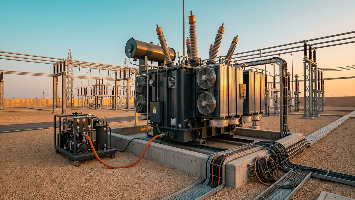
The entire facility’s power journey begins at the point of common coupling with the high-voltage transmission network, which could operate at levels like 132 kV, 275 kV or 400 kV. The first critical components are the main power transformers connecting the plant to this grid. These are large, gantry-mounted units responsible for stepping the transmission voltage down to a more manageable medium voltage for distribution across the expansive site, typically 33 kV. Given the fluctuating power output from associated renewable sources and the variable loads within the plant, these transformers are almost always equipped with On-Load Tap Changers (OLTCs). The OLTCs provide crucial voltage regulation, adjusting the transformer’s turns ratio dynamically to maintain a stable output voltage under shifting load conditions. This stability is paramount, as voltage deviations on the internal 33 kV bus would disrupt the sensitive operations of the downstream desalination, electrolysis, and synthesis systems, making these initial step-down transformers the gatekeepers of the plant’s overall power quality and reliability.
Rectifier Transformers: The Heart of Electrolysis
The most unique power conversion challenge lies in feeding the PEM electrolysers. A standard power transformer cannot be used for this application, as it is not designed to handle the operational stresses imposed by the AC-to-DC conversion process. This task requires a specialised rectifier transformer. An electrolyser does not present a smooth, linear load to the network; instead, it draws current in short, non-sinusoidal pulses. This distorted current waveform is rich in harmonic frequencies, which create additional heat (I²R losses) in the transformer’s windings and core. Rectifier transformers are engineered to accommodate these harmonic losses through specific design considerations, such as the use of continuously transposed conductors or specialised winding arrangements to mitigate circulating currents. Furthermore, the rapid switching of the rectifier’s power electronics subjects the transformer windings to high-frequency voltage spikes and significant electromagnetic forces. The windings must be mechanically braced far more robustly than in a standard transformer to withstand these repetitive stresses throughout their operational life. Without this purpose-built design, a conventional transformer would face rapid thermal aging and eventual dielectric or mechanical failure.
Managing Harmonics with Multi-Pulse Rectification
While rectifier transformers are built to withstand harmonics, the primary strategy is to cancel them at the source. This is accomplished by using multi-pulse rectifier topologies, most commonly 12-pulse or 24-pulse configurations for large-scale electrolyser applications. A 12-pulse system employs a rectifier transformer with two secondary windings: one connected in a delta configuration and the other in a wye configuration. This arrangement creates a 30-degree phase shift between the two secondary voltages. When these two outputs feed their respective six-pulse rectifier bridges, the combined DC output is smoother, and more importantly, the phase shift causes the 5th and 7th order harmonic currents—the most significant in a standard six-pulse system—to be cancelled out at the primary winding. A 24-pulse system takes this principle further, using more complex phase-shifting transformers to feed four separate rectifier bridges. This cancels harmonic orders up to the 23rd, resulting in a current waveform that is much closer to a pure sine wave. This is critical for meeting stringent grid code requirements, such as IEEE 519, which limit the amount of harmonic distortion a plant can inject into the public network, thereby preventing interference with other grid-connected users.
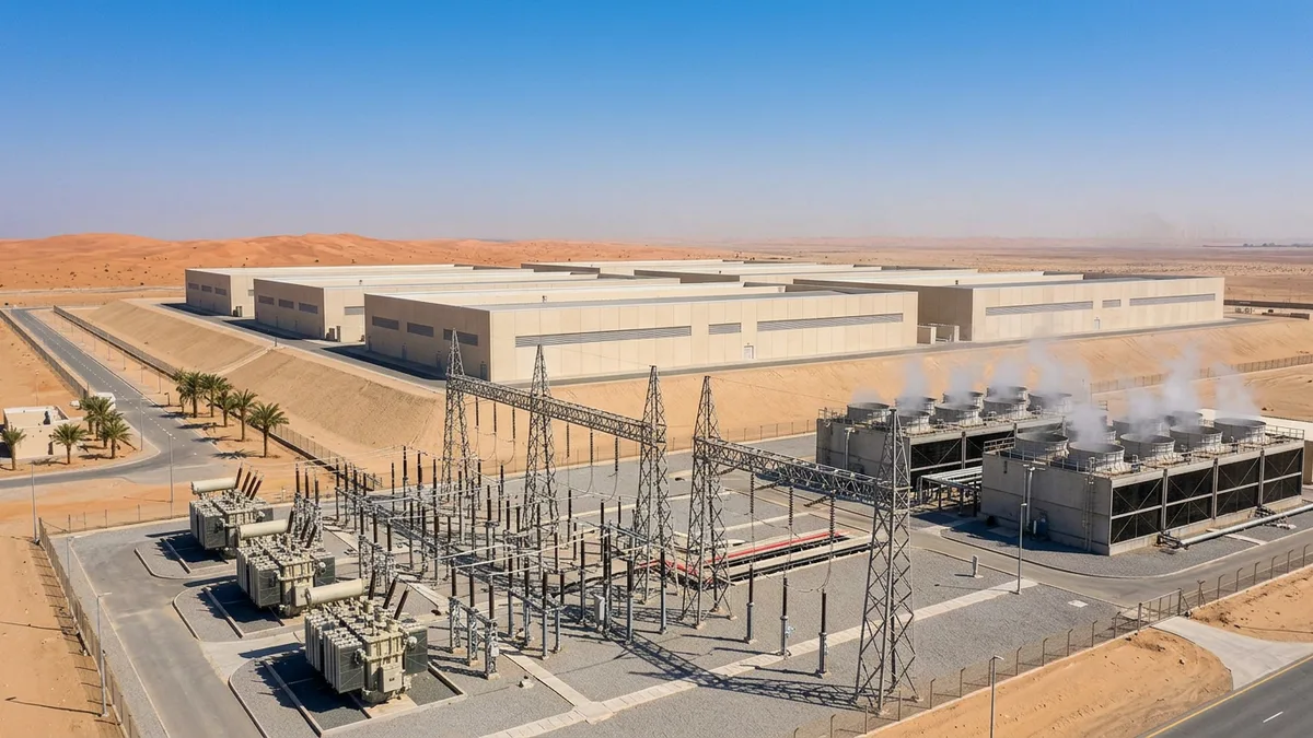
Powering Synthesis and Auxiliary Systems
Once green hydrogen is produced, it must be converted into a more practical form for storage and transport. In many coastal and solar-rich regions, this means synthesising ammonia, a process that requires its own robust power infrastructure. The synthesis loop involves compressing the hydrogen and nitrogen gases to high pressures and heating them in a reactor. This equipment is powered by large AC motors and resistive heating elements, which constitute a more conventional industrial load. The power for this part of the plant is supplied by a fleet of auxiliary and distribution transformers. These units step the internal medium voltage (e.g., 33 kV) down to a usable low voltage, such as 400V, to power motor control centres, lighting, HVAC, and control systems. While these transformers may seem more standard, their reliability is no less critical. An unexpected failure in a single distribution transformer powering a key compressor or control room could halt the entire synthesis process, creating a major production bottleneck. Therefore, these units, whether oil-filled or dry-type/cast-resin for indoor applications, are specified for high reliability and low losses to ensure the continuous and efficient operation of the plant’s back end.
Ultimately, transforming seawater into a green fuel is an exercise in precise power-flow management. The engineering challenge is not simply the delivery of bulk megawatts, but the meticulous conditioning of that power to suit disparate industrial processes. The critical interface remains the connection between the AC grid and the DC electrolyser, where the combination of specialised rectifier transformers and multi-pulse harmonic cancellation techniques provides the foundational technology enabling the entire e-fuel production chain. The core engineering truth is that managing harmonic currents and voltage stability is as vital as managing the flow of energy itself. The success of such a venture is measured in power quality as much as in power quantity.