When a modern metro train glides to a smooth, precise halt at its station, the process feels effortless. This deceleration, however, involves immense kinetic energy that must be managed. Instead of simply relying on friction, the train's own electric motors act as generators, converting forward momentum back into electrical power. This energy, pushed back onto the third rail or overhead catenary, presents both an opportunity and a significant challenge for the engineers designing the traction power system.
The Physics of a Train Pushing Back
At its core, regenerative braking leverages the inherent duality of a DC electric motor. When electricity is applied to the motor, it creates a magnetic field that turns the rotor and drives the train's wheels. Conversely, when the train is decelerating and the wheels are forced to turn the motor, it functions as a generator. The kinetic energy of the moving train is converted into electrical energy. This generated voltage is slightly higher than the nominal voltage of the DC traction line—for example, higher than 750 V or 1500 V DC. According to Ohm's law, this higher potential causes current to flow from the train back into the power distribution system. This is the "push back" of the article's title. This process is fundamentally more efficient than its alternatives. In traditional rheostatic braking, this generated electricity is shunted to large on-board resistor banks, where it is purposefully wasted and dissipated as a significant amount of heat. Mechanical braking, using brake pads and discs, also converts kinetic energy to heat through friction, causing wear and tear. Regeneration offers a way to reclaim and reuse a substantial portion of the energy that was initially expended to accelerate the train, improving the overall energy efficiency of the rail system.
The Receptive Train Assumption
The most efficient and desirable destination for this regenerated power is another train on the same electrical section of the line. In the ideal scenario, as one train brakes approaching a station, another train is simultaneously accelerating as it departs. The power generated by the braking train flows directly through the shared DC catenary or third rail to the accelerating train, which consumes it. The traction power substation, which normally feeds power from the grid to the trains, may see little to no net load during this exchange. This peer-to-peer energy transfer is the most elegant use of regenerative braking. System planners for high-density urban metro lines often rely on this "receptive train assumption." They calculate that with short headways between trains, particularly during peak hours, there will almost always be an accelerating train nearby to absorb the regenerated energy from a braking one. This assumption allows for a simpler, less expensive substation design. However, it is an assumption that can and does fail under certain conditions, such as during the first or last service of the day, on less-trafficked parts of the network, or during unexpected service disruptions that alter normal train spacing.
Passive Substations and the Problem of Excess Energy
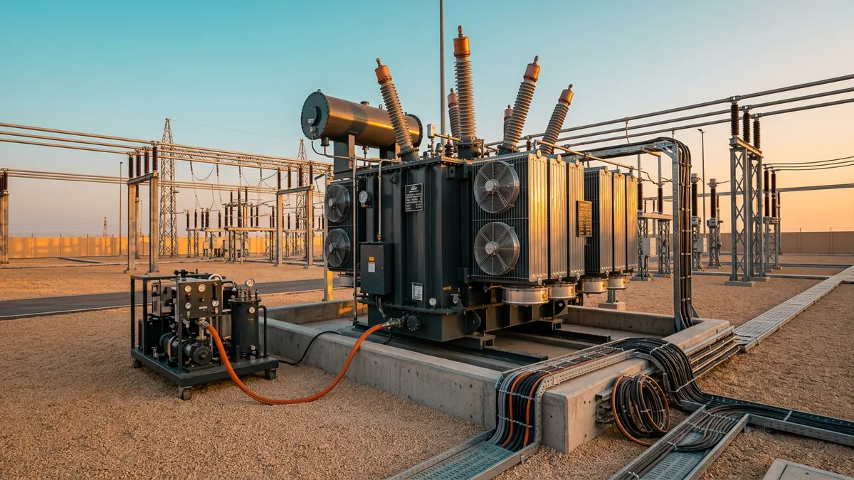
What happens when there is no receptive train to absorb the braking energy? The answer lies in the design of the traction power substation. The most common type is a passive, diode-based rectifier substation. Its primary function is to convert the high-voltage alternating current (AC) from the utility grid into the direct current (DC) needed by the trains. These substations use diodes, which are semiconductor devices that function like one-way valves for electricity. They efficiently allow power to flow from the AC grid to the DC traction network but physically cannot allow it to flow in the reverse direction. As a braking train pushes power back with nowhere to go, the voltage on the DC line begins to rise rapidly. To prevent this overvoltage from damaging the train's own equipment or the substation, a pre-set voltage limit is established. Once this ceiling is reached, the train’s on-board protection system automatically activates its rheostatic braking resistors. The regenerated energy, having been momentarily saved, is then deliberately burned off as heat into the tunnel or surrounding environment. While this method is robust, reliable, and safe, it forfeits all the potential energy savings of regeneration whenever a receptive load is not immediately available on the line.
Active Substations: Enabling Two-Way Power Flow
An increasingly common solution to the limitations of passive substations is the use of active, or "inverting," substations. These systems replace the simple diodes with a more sophisticated power electronics converter, typically using Insulated-Gate Bipolar Transistors (IGBTs) or similar controllable semiconductor switches. This architecture is often referred to as an Active Front End (AFE). An AFE can manage power flow bidirectionally. Under normal conditions, it functions as a rectifier, supplying DC power to the trains. However, when it detects a rise in DC voltage from regenerative braking, its high-speed controllers can instantly reconfigure its operation. It begins to function as an inverter, taking the excess DC power from the traction line, synthesizing a clean AC waveform that is perfectly synchronised in voltage, frequency, and phase with the utility grid, and feeding the power back into the local medium-voltage network. This not only maximizes energy recovery but also provides much tighter control over the DC line voltage, improving stability for the entire system. Furthermore, AFE substations can be programmed to have a near-perfect power factor and can mitigate harmonic distortions, making them a much "friendlier" load on the utility grid compared to older diode rectifiers.
System-Level Design and Utility Constraints
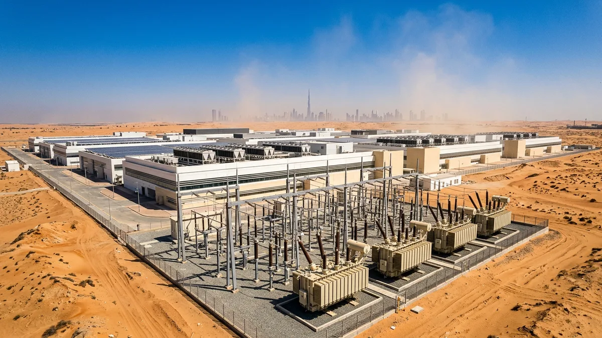
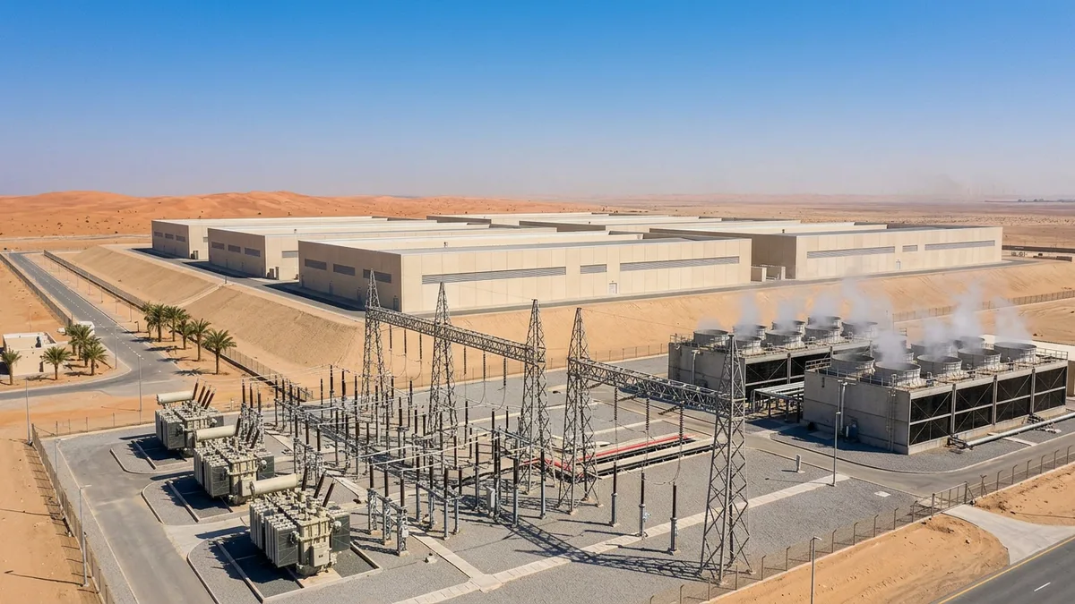
The choice to implement inverting substations is not purely a technical one; it involves the entire energy ecosystem. Even if a transit operator invests in a fully regenerative AFE substation, the local utility provider must be able to accept the intermittent and highly variable reverse power flow. In some cases, the local distribution grid may not have the capacity or stability to absorb these sudden injections of power. The utility's own protection systems might interpret the reverse flow from the metro as a fault condition. Therefore, detailed interconnection studies and agreements are a critical prerequisite. Engineers must analyse the "fault level" and stiffness of the connected grid to ensure it can handle the load. These system-level considerations are paramount, especially in rapidly developing areas where the electrical grid itself is being built out concurrently with the transportation network. The decision involves a complex trade-off between the higher capital expenditure of AFE substations and the long-term operational savings from reduced energy consumption and the potential revenue or credits from feeding power back to the grid.
Ultimately, how a metro system handles regenerated energy is a defining choice in its electrical design philosophy. While the receptive train assumption provides a baseline for efficiency, the move towards bidirectional, inverting substations reflects a more holistic approach to energy management. The decision balances the capital cost of advanced power electronics against the operational benefits of full energy recovery, all while navigating the constraints and capabilities of the broader utility grid to which it is inextricably linked.