The air in the rectifier hall hums with a deep, uniform note, a resonant baritone that you feel in your bones long before you can place it. It is the sound of pure, relentless power conversion on a scale that exists in only a handful of industries. Here, in the electrical heart of an aluminium smelter, alternating current from the high-voltage grid is transformed and rectified into the massive, direct current feed required for the electrolysis that turns alumina into metal. For an aluminium pot-line, electricity is not the energy that drives the machinery; it is the raw material itself, consumed in a continuous, ravenous process unlike any other.
From a Wave to a Line: The DC Imperative
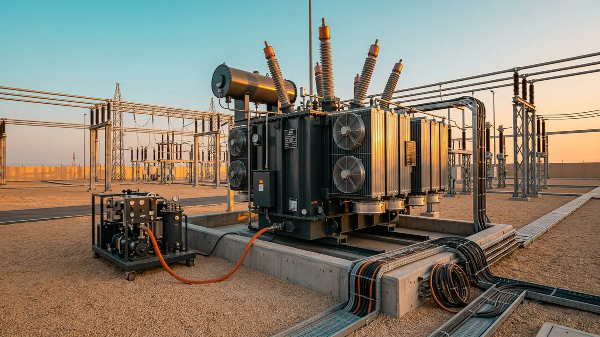
The Hall–Héroult process for smelting aluminium is fundamentally a DC-powered phenomenon. The electrochemical reaction that liberates aluminium from its oxide bond requires a constant, unidirectional flow of current through the electrolytic cells, or "pots". The grid, however, delivers power as three-phase alternating current (AC). Bridging this gap is the job of the rectifier station, arguably the most critical and challenging electrical system in the entire facility. The core components are large rectifier transformers and the rectifiers themselves—typically high-power diode or thyristor assemblies. These systems take incoming high-voltage AC, such as 132 kV or 275 kV, step the voltage down dramatically, and convert the alternating sine wave into a stable DC output. The sheer amperage required is staggering, creating immense thermal and electromagnetic stresses that dictate every aspect of the equipment’s design, from the busbar dimensions to the cooling systems. The reliability of this AC-to-DC conversion is paramount; even a brief interruption can cause the molten electrolyte in the pots to cool and solidify, a catastrophic failure that can halt production for months.
Transformers Built for a Different War
A rectifier transformer is a fundamentally different machine from a standard grid or generator step-up transformer. While a grid transformer is designed for relatively balanced, sinusoidal loads, a rectifier transformer must withstand the severe duty imposed by the non-linear, non-sinusoidal currents drawn by the rectifier bridges. Governed by standards like IEC 61378, their design prioritizes robustness against harmonic currents and extreme thermal loading. The secondary windings feeding the rectifier are engineered for immense currents and are subject to DC voltage stress. This requires specialised winding configurations and reinforced insulation. Furthermore, to manage the complex magnetic fields and harmonic fluxes, the core and tank are often designed with non-magnetic shields. Eddy currents and stray losses, which are secondary considerations in conventional transformers, become primary design challenges here. These units are not merely stepping down voltage; they are the first line of defence, conditioning the power and absorbing the punishment that would destroy a standard network transformer.
The Pulse of the Machine: 12- and 24-Pulse Systems
To refine the raw rectified DC and reduce its inherent "ripple" voltage, smelters universally employ multi-pulse rectifier configurations. A simple six-diode bridge produces a DC output with significant voltage fluctuation—it is a rough, "lumpy" current. By using two or more six-pulse bridges phase-shifted from each other, a smoother DC output can be achieved. A common topology is the 12-pulse rectifier, which uses two bridges fed by a transformer with two secondary windings, one wye-connected and one delta-connected. This creates a 30-degree phase shift between the two secondary systems. The resulting combined DC output is significantly smoother, and just as importantly, it cancels out several of the most problematic lower-order harmonic currents (the 5th and 7th) on the AC side. For even larger installations or where grid codes are stricter, 24-pulse or even higher-order systems are deployed. A 24-pulse system combines four six-pulse bridges with precise phase shifts, resulting in an even cleaner DC voltage and eliminating more harmonic orders, further reducing stress on the upstream power network.
***
Quick Reference: Grid vs. Rectifier Transformers
***
Taming the Noise: Harmonics and Power Quality
While 12- and 24-pulse rectifier topologies are effective, they do not eliminate harmonic distortion entirely. They merely shift the problem to higher-order, but a significant amount of harmonic "noise" is still injected back into the AC supply system. This distortion degrades power quality, and if left unmanaged, it can cause protective relays to malfunction, overheat generator windings, and interfere with sensitive electronic equipment across the entire grid. To counteract this, large smelter rectifier stations are equipped with extensive AC harmonic filter banks. These are passive circuits, typically consisting of large capacitors, reactors, and resistors, installed on the high-voltage AC side of the rectifier transformers. Each filter bank is tuned to a specific harmonic frequency (e.g., the 11th, 13th, 23rd, 25th). By presenting a low-impedance path to ground, these filters effectively trap and absorb the unwanted harmonic currents before they can propagate into the wider power system, ensuring compliance with grid code requirements for power quality.
The Unseen Load: Reactive Power Compensation
The immense phase-controlled rectifier systems in a smelter are significant consumers not just of real power (megawatts), but also of reactive power (MVAr). This large inductive load results in a poor power factor, meaning the AC system must supply more current than is being put to productive use, leading to inefficiencies and potential voltage stability issues on the grid. The harmonic filter banks play a dual role here. Being capacitive in nature at the fundamental frequency (50 or 60 Hz), the filter banks inherently provide a substantial amount of leading reactive power. This capacitive effect compensates for the lagging reactive power drawn by the rectifiers. The system is carefully engineered so that the filters, while primarily there for harmonic mitigation, also provide the precise amount of reactive power compensation needed to maintain a healthy power factor close to unity, satisfying the demands of both the smelter and the grid operator.
The intricate dance between the rectifier transformers, pulse configuration, and harmonic filters is a masterclass in high-power electrical engineering. The design of the transformer windings directly influences the harmonic profile, which in turn dictates the tuning and scale of the filter banks. The entire system must be viewed holistically, as a single power-conditioning machine engineered to present a stable, predictable, and clean load to the grid while delivering an unwavering river of DC to the pots. The real achievement lies not just in handling the colossal power, but in making it appear almost benign to the electrical network it leans upon.