Texas built a grid that lives off natural-gas inertia and now finds itself replacing it with software. ERCOT's synthetic-inertia services compensate grid-forming inverters for emulating a synchronous machine, and the duty profile that arrives at a 34.5/138 kV battery step-up looks nothing like the load profile in the original capability data sheet. The economics are real; the engineering catches up slower.
The Grid-Following Inheritance
Not so long ago, the job of an inverter-based resource (IBR)—solar, wind, or battery—was simple: make hay while the sun shines (or the wind blows), convert DC to AC, and push megawatts onto a grid that was assumed to be infinitely strong and stable. The inverters themselves were “grid-following” (GFL). They saw the grid as an immutable voltage and frequency source, and their primary protective instinct was self-preservation. See a fault? Trip offline in milliseconds. This philosophy, codified in early versions of IEEE 1547, was perfectly logical when IBRs were a rounding error in the generation mix.
This behavior shaped the entire balance-of-plant ecosystem. Why would an EPC or developer specify a GSU transformer capable ofwithstanding severe through-faults if the inverter it was connected to was designed to disconnect at the first sign of trouble? They wouldn’t. Transformers for GFL solar and BESS plants were specified based on steady-state load, MVA rating, and basic impedance characteristics. They were engineered for efficiency and cost, not for the repeated mechanical and thermal shocks of fault ride-through. The GSU was a passive, almost pedestrian, component. Its main job was voltage transformation, and its protective envelope was built around the inverter’s cowardice.
For a decade, this worked. But as gigawatts of solar and wind displaced spinning masses of steel at gas and coal plants, the grid’s intrinsic inertia began to plummet. Small disturbances that would have once been absorbed by the rotational energy of a thousand generators now cause alarming frequency deviations. The Odessa Disturbance in Texas, where a single fault tripped over 1.1 GW of solar resources, was a blaring wake-up call. The grid-following model was no longer sustainable.
ERCOT Ups the Ante
In response to this growing fragility, grid operators like ERCOT have moved aggressively to demand more from IBRs. The new mandate, crystallized in rules like ERCOT’s Nodal Protocol Revision Request (NPRR) 1186, requires new (and some existing) BESS resources to be “grid-forming.” Instead of just following the grid’s lead, GFM inverters are capable of creating their own voltage and frequency reference. They can operate as a voltage source, providing “synthetic inertia” to counteract grid disturbances.
This is a monumental shift. A GFM inverter mimics the behavior of a traditional synchronous generator. When it sees a voltage dip from a nearby fault, it doesn’t trip offline. Instead, it injects a massive pulse of reactive current to support the grid voltage. How massive? The emerging consensus, and ERCOT’s specific requirement, is a short-circuit current contribution of up to 2.0 per unit (p.u.) of the inverter’s rating.
Herein lies the problem for the unassuming GSU. A GFL inverter’s transformer might see a major through-fault once or twice in its life. A GFM inverter’s transformer will see it every single time a fault occurs on an adjacent feeder. This isn’t an exceptional event; it’s a design condition. This new duty cycle imposes two distinct physical stresses that legacy transformer designs are simply not prepared to handle:
- Electromagnetic Forces: The raw force experienced by a transformer’s windings is proportional to the square of the current. A jump from a near-zero fault contribution (for a GFL that trips instantly) to a 2.0 p.u. surge is an exponential increase in physical stress. This force tries to push the windings apart, fatiguing the bracing structures and potentially causing catastrophic failure over time. For a transformer not explicitly braced for this duty, every grid support event is a roll of the dice.
- Thermal Shocks: While the current injection is brief (typically lasting only a few cycles), the heat generated is immense. This isn’t a slow, steady-state temperature rise that fans can dissipate; it’s a sharp thermal shock to the winding insulation. Repeated shocks accelerate the aging of the paper insulation, reducing the transformer’s dielectric strength and overall lifespan. An EPC using standard thermal calculations based on FLA (Full Load Amps) is missing the most critical failure mode.
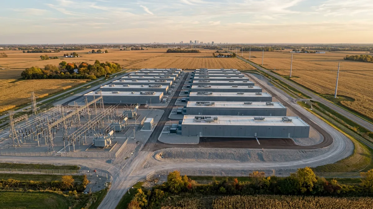
Suddenly, the GSU is no longer a passive component. It’s an active participant in grid stability, and it is often the weakest link in the chain. More information on GSU and substation design can be found on our packaged substations page.
The Transformer Specification Gap
This new reality creates a dangerous gap between how transformers *have been* specified and how they *must be* specified for GFM applications. Relying on a spec sheet from a 2018 solar farm is a recipe for disaster. The IEEE C57.12.00 standard, the bible for transformer design, provides guidance on through-fault duration curves. However, these curves were developed with conventional faults in mind, not the high-frequency, repetitive duty cycle that GFM inverters will impose.
Engineers and procurement managers must now ask questions that were previously considered secondary:
1. What is the transformer’s cumulative through-fault capability? The specification can no longer be a simple MVA rating. It must account for the number, magnitude, and duration of expected fault events over the asset’s 25-year lifespan.
2. Is the winding and core bracing sufficient? The mechanical design of the transformer’s internal assembly is now paramount. Vetting a manufacturer’s bracing philosophy and test reports is critical. A low-bid transformer is unlikely to have the robust internal structure required.
3. How is impedance optimized? There is a new trade-off to consider. A lower impedance GSU allows for higher fault current contribution, which the grid operator wants, but it also increases the electromagnetic forces on the windings. A higher impedance unit might be safer for the transformer but could limit the BESS plant’s ability to meet its GFM obligations. This requires careful system-level analysis, not just component-level procurement.
4. Are the thermal models adequate? The manufacturer’s thermal calculations must go beyond ANSI/IEEE loading guides and specifically model the rapid, short-duration heating from GFM fault injection. This may require more sophisticated finite element analysis (FEA) modeling.
Treating the GSU as a commodity is a path to premature failure, costly outages, and liquidated damages for failing to meet interconnection agreement requirements. For a deeper dive into GFM-ready designs, see our core transformer products.
Future-Proofing for a GFM World
For developers with large fleets of IBRs, the GFM mandate presents a significant challenge. For new builds, the solution is straightforward, if more expensive: specify mechanically robust, GFM-rated GSU transformers from day one. The incremental capital cost of a properly specified transformer is trivial compared to the cost of a failure and the associated lost revenue.
Retrofitting is a thornier issue. Many solar plants built between 2015 and 2022 are now being asked to add BESS and enable GFM capabilities. Their existing GSU transformers are almost certainly not rated for this new duty. Asset owners face a difficult choice:
- Replace the GSU: A costly and disruptive option, but the most technically sound.
- Derate the Inverter: Program the GFM inverter to provide a lower fault current (e.g., 1.5 p.u. instead of 2.0 p.u.), which may protect the transformer but risks non-compliance with ERCOT or other ISOs.
- Accept the Risk: Operate the plant as requested and hope the legacy transformer holds up. This is a high-stakes gamble on an aging asset.
Ultimately, the transition to a GFM-dominated grid forces the industry to re-evaluate its entire approach to balance-of-plant engineering. The era of treating the GSU as a simple, off-the-shelf component is over. It is now a critical piece of grid-support infrastructure that demands the same level of engineering rigor as the inverters themselves. If you have questions about your specific application, you can always contact our engineering team.
The Engineer's Takeaway
The inverter might get the headlines for providing synthetic inertia, but it’s the humble step-up transformer that will determine whether the plant is able to deliver it reliably. While ERCOT writes the rules, it's the laws of physics—specifically electromagnetics and thermodynamics—that will govern the outcome. It's time to update your GSU specification before the grid does it for you.