Modular multilevel converter topologies cleaned up the harmonic spectrum on the AC side compared with the line-commutated HVDC of an earlier generation. They did not eliminate it. The converter transformer at a 1.4 GW North Sea export platform — a typical Dogger Bank or Hornsea Three asset — must absorb a non-trivial harmonic content as a continuous duty. Its design margins, and the failure modes when those margins are squeezed, are the focus here.
The Gravity of the Situation
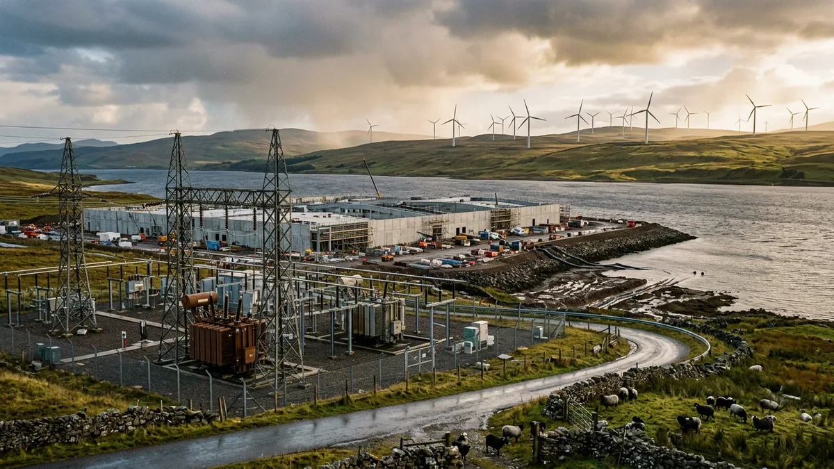
An offshore HVDC converter platform is, first and foremost, a very heavy object that must not fall into the sea. Before any electrons flow, the defining challenge is structural. The single heaviest components on the topside are the converter transformers. For a typical 1 GW bipole configuration, this means two units, each weighing 300–450 tonnes, plus a spare. These are not catalogue items. They are bespoke machines designed to meet exacting specifications like IEC 60076, while also being compact and robust enough for a sea voyage and a life in a salt-mist environment.
This mass dictates everything. It drives the design of the topside module, the load-bearing capacity of the jacket foundation pinned to the seabed, and the choice of heavy-lift vessel for installation. When a utility like TenneT or National Grid ESO specifies a 320 kV DC link voltage for a project like DolWin6 or Sofia, it is not simply an electrical decision. While 525 kV offers superior transmission efficiency, the associated transformers and converter equipment bring a weight penalty that can exceed the limits of available jacket designs or installation fleet capacity. The 320 kV system, refined across dozens of North Sea projects, represents a known quantity for weight, footprint, and reliability. This pragmatism is why the current generation of German, Dutch, and British offshore wind connections have coalesced around this voltage level. It is the engineering sweet spot between electrical performance and the sheer, immovable physics of steel and gravity.
Converter Symmetries: VSC vs LCC
The heart of the platform is the converter hall. Here, AC from the wind turbines is converted to DC for transmission to shore. The choice of converter technology has more impact on the platform design than any other system. The two main families are Line-Commutated Converters (LCC) and Voltage-Source Converters (VSC).
LCC technology, using thyristors, is mature and efficient. It is the backbone of classic point-to-point HVDC schemes. However, it has two significant drawbacks for offshore wind. It requires a strong AC network to commutate, meaning it cannot start up a dead network (a ‘black start’). It also consumes reactive power and generates significant low-order harmonics, necessitating vast banks of AC filters and capacitors. On a constrained offshore platform, the footprint and weight of this ancillary equipment make LCC a non-starter.
VSC technology, using IGBTs, is self-commutated. This gives it the ability to create its own AC voltage, control reactive power independently, and perform a black start. These are essential features for connecting intermittent wind generation to the grid. Early VSC designs used a two-level topology which, while functional, had high switching losses and still required harmonic filters. The definitive breakthrough for offshore applications was the Modular Multilevel Converter (MMC), a VSC topology that builds the AC waveform from many smaller sub-modules. This approach produces a near-perfect sine wave with very low harmonic distortion, drastically reducing the size of filters needed. It also offers lower losses and inherent redundancy.
HVDC Converter Technology Comparison for Offshore Wind
For offshore wind, the VSC-MMC is the undisputed choice. The trade-off is higher converter complexity against a dramatic reduction in passive components and a superior grid-forming capability that transmission operators value highly.
Pleasing the System Operator: Harmonics and Grid Code
Connecting a multi-gigawatt power source to a national grid is not a private matter. In Great Britain, the process is governed by National Grid ESO through the Grid Code and the G99 engineering recommendation. Similar frameworks exist in Europe, with TenneT in Germany and the Netherlands imposing famously stringent requirements. A key chapter in this rulebook concerns power quality, specifically harmonic emissions.
An LCC converter injects significant harmonic currents at frequencies defined by its pulse number (5th, 7th, 11th, 13th for a 6-pulse system). To meet strict utility limits like those in IEEE 519 or the Grid Code’s planning levels, LCC systems require enormous, tuned passive filter banks. These are heavy, bulky, and can have complex interactions with the wider AC network.
A VSC-MMC converter, by contrast, is a paragon of electromagnetic compatibility. By using a large number of levels, it produces an AC waveform so clean that it often requires only small high-frequency filters, or none at all. This is a profound advantage for an offshore platform. It shrinks the topside footprint, reduces weight, and eliminates the risk of adverse harmonic interactions with the wind turbine arrays or the onshore grid. This inherent low-harmonic output is a primary reason why MMC technology enables compliance with strict codes like G99 without the heavy engineering compromises of LCC.
For a project like Hornsea 3, demonstrating G99 compliance is a multi-year process involving detailed modelling and simulations long before any steel is cut. The choice of VSC-MMC topology fundamentally de-risks this process.
Steel on the Seabed, or Steel on the Move
The default image of an offshore platform is a steel jacket fixed to the seabed. This has been the standard for oil and gas and for the majority of HVDC platforms to date, including those at Dogger Bank. This approach is well understood, but it has limits. As wind farms move into deeper waters, the required size, weight, and cost of a fixed-bottom jacket escalate rapidly. At depths beyond 60-70 metres, they become technically and economically unfeasible.
The industry is therefore watching the development of floating platforms and new fixed-bottom concepts with interest. Projects like TenneT’s DolWin6, which uses a more compact topside, and the planned installation of BorWin5 signal a move towards lighter, more efficient designs. Full-floating solutions for HVDC converter stations are still in the concept stage, facing challenges with the dynamic behaviour of the platform and the high-voltage riser cables connecting it to the seabed export lines.
Regardless of the foundation type, the operational reality of the North Sea intrudes. Maintenance is planned around narrow weather windows. Access is primarily by helicopter, mandating a certified helideck. Crew Transfer Vessels (CTVs) with dynamic positioning can be used in calmer seas, but for two-week stretches in winter, the platform may be entirely isolated. This drives a design philosophy favouring redundancy, remote monitoring, and minimal human intervention.
The Deciding Factor: Cost per Kilometre
For all the technical nuance, the ultimate decision between sending power to shore via High-Voltage AC (HVAC) or HVDC comes down to distance and power. HVAC is simple and reliable for short distances. However, the physics of subsea cables introduce a problem: capacitance. An AC cable acts as a large capacitor, requiring significant reactive charging current. Over distances greater than about 80 kilometres, this charging current consumes so much of the cable’s capacity that there is little left for transmitting useful power.
HVDC has no such issue. A DC cable has no capacitive charging current, meaning power can be transmitted over hundreds of kilometres with only resistive losses (I²R). The breakeven point is where the high cost of the converter stations at each end is offset by the savings of the cheaper, more efficient DC cable and the avoidance of intermediate reactive compensation platforms. For the gigawatt-scale wind farms being built 100-200 km from the coasts of Yorkshire or Lower Saxony, HVDC is the only viable technical solution.
The economic case is not just about viability, but about cost per megawatt landed. By aggregating the output of hundreds of turbines onto a single HVDC link, developers achieve an economy of scale that would be impossible with multiple HVAC cables. It is here, in the cold calculus of capital expenditure, that the complex engineering of an offshore HVDC platform finds its justification.
Further Analysis
The trade-offs in offshore platform design are continuous and multifaceted. The balance between topside weight, electrical efficiency, and grid compliance remains a primary focus for designers at firms like Petrofac and Siemens Energy. As wind farms push further from shore and into deeper waters, the pressure to innovate on platform design, converter technology, and installation methods will only increase.
Related reading from our blog:
- A Deep Dive into Subsea Cable Joint Reliability
- Navigating G99: A Guide for VSC-HVDC Connections
- The Economics of Offshore Transmission: HVAC vs HVDC at Scale